Shortlink

Quadcopter Parts List

QuadCopter_Shot

I got all the parts in this list from HobbyKing

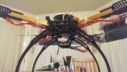
1 Hobbyking X650F Glass Fiber Quadcopter Frame 550mm
4 TURNIGY Plush 30amp Speed Controller
4 NTM Prop Drive 28-26 1000KV / 315W (short shaft version)  (Note: I think these motors are actually too small; want to put 35’s at 700 – 900 kv)
1 Turnigy 3000mAh 3S 30C Lipo Pack
1 OrangeRx R620 Spektrum/JR DSM2 Compatible Full Range 6Ch 2.4Ghz Receiver w/Failsafe
4 NTM Prop Drive 28 Series Accessory Pack
1 Slow Fly Electric Prop 9047R SF (4 pc Right Hand Rotation) (Note: The 28’s really have to work to get this off the ground with this prop)
1 Slow Fly Electric Prop 9047SF (4 pc)  Note: The 28’s really have to work to get this off the ground with this prop)
1 10×4.5 SF Props 2pc Standard Rotation/2 pc RH Rotation (Red) Note: This prop works much better with the 28’s
1 TURNIGY BESC Programming Card (Note: Optional, but really really useful)
1 Multiwii and Megapirate AIO Flight Controller w/FTDI (ATmega 2560) V2.0
1 NEO-6M GPS Module (Note: Technically not required, but I knew I was going to do some GPS stuff)
1 HXT 4mm to 4 X 3.5mm bullet Multistar ESC Power Breakout Cable
1 HXT 4mm Gold Connector w/ Protector (10pcs/set)
2 PolyMax 3.5mm Gold Connectors 10 PAIRS (20PC)
1 Turnigy 4mm Heat Shrink Tube – RED (1mtr)

Cost of parts: $289.93Cost of shipping: $52.75
Total: $342.68

There were a couple items that I forgot to get from HobbyKing:

Screws and nuts to mount the motors to the frame; ideally 16 3mm x 7-8mm; I only used 8 however since the motor ‘x-bracket’ doesn’t fit exactly on the frame.
Foam padding as vibration isolation for the flight computer.  I used some foam that like memory foam.

Item that I don’t have an not sure where to get yet:

The AIO Pro has 6 pin Molex connector and the GPS unit has a 5 pin Molex connector.  So, I need to remove the 5 pin and put a 6 pin on it.  It is a serial interface so I’m not sure why they are different.

Item that I will purchase next:

3DR Radio Telemetry Kit – 915 Mhz (US) – Sends telemetry data back to computer or phone

Shortlink

Quadcopter Build – Intro

I’ve decided to build an RC Quadcopter.  I’ve currently got an AR Drone 1.0, Nano QX and a 1SQ V-CAM.  The new one is going to be built from parts rather than an ‘Ready to Fly’ or ‘Almost Ready to Fly’ (RTF or ARF).

There are four major components to the quadcopter:

  1. Frame
  2. Power Plant
  3. Flight Control System
  4. Transmitter/Receiver

Frame:

Quadcopter is a class of Multi-Rotor Copters; they can can three, four, six or even eight motors!  Quadcopters offer a good balance of lift capability and cost.  Hex and Octo-copters give more stability and failure control, however, they are more expensive.  Tri-Copters are less expensive, but less stable and have less lift capability.

I’ll be building a Quad-Copter.  The frame I chose is a HobbyKing X650F Glass Fiber Frame.  Looks nice and strong, has plenty of room to mount the Flight Control System and has a camera mount.  Built out it will 550mm (~21 inches) wide.  I think the key for a frame is that it be level and rigid; the motors all need to be at the same level and mounted square to the ground and parallel to each other.

Power Plant:

When I placed the order I pretty much just took a shot in the dark with respects to the motors and props.  With the power system you have the battery, motors, electronic speed controllers (ESC), propellers and wiring harness.  Not sure how mine will turn out; I took a shot in the dark with respect to the motor sizes and I got two sizes of props (. x 4.7 and 10 x 4.5)  The motors are 28-26 NTM motors at 1000 KV (RPMs/v); that might be a tad fast.  We’ll have to see how it works.  I’ve got 3000mAH battery for it and I’m expecting somewhere around 7 min flight times.  Finally, everything needs to be wired up.  There is a power distribution harness that splits the power from the battery to the four ESCs and then to Flight Control System.  The trickiest part here is matching up all the connectors on all the parts; but that has always been an issue with electrics RC stuff.

Flight Control System:

I’m using a HobbyKing “MultiWii and MegaPirate All-In-One Pro” flight computer.  It is basically an Arduino Mega 2560 w/ an Accelerometer, gyroscope, barometer and magnaometer, I2C port, FTDI port, and 2 serial ports.  It can use MultiWii or MegaPirate software packages for handling all the inputs (receiver and sensors) and setting the motor speeds.  I decided to start with MultiWii; just because it was the first one I came across.

MultiWii can be downloaded from http://code.google.com/p/multiwii/

MegaPirate can be downloaded from http://code.google.com/p/megapirateng/

Transmitter/Receiver:

I’m using a Spektrum DX6I 6 channel transmitter and I paired it with a very inexpensive Orange DSM2 receiver.  The transmitter for quadcopters are normally setup in ‘Acro’ mode.  This is because the ‘Heli’ mode does the mixing of the channels in the transmitter, but the Flight Computer does the mixing for quadcopters.  So, we don’t typically want to do much mixing in the transmitter.

Shortlink

RobotC / Arduino Controller

The latest controller to fall under to control of RobotC is the Arduino!  While programming the Arduino w/ it’s existing development environment is not really all that complex, RobotC does bring some significant capabilities and advantages to the table.

  • Interactive debugging
  • Easy access to a host of sensors
  • Easy learning curve lowered for those FIRST Robotics fans (FIRST Tech Challenge specficially)
  • Possibly be able to simulate multi-tasking (fast task switching)

If you are interested in finding out more about this head over to robotc.net to download the demo and start playing with it today!

Shortlink

Arduino Temp Monitor Progress

I’ve finally made some time to work on the temperature monitor for the server room.

The Temperature Monitor currently consists of an Arduino Uno R3, Ethernet Shield and a small prototyping board.

It will currently listen to port 80 on an internal IP address. When a request comes in it will create a simple web page that shows the raw value from the sensor, degrees Kelvin, degrees Celsius and degrees Fahrenheit. In addition to the web page there is an RGB LED that reflects the current temperature. The picture below shows the simple web page and the color scale for the RGB LED.

The prototype board consists of the two sections:

Temperature Monitor:
LM335A temperature sensor, 2K ohm resistor and a 10k ohm potentiometer.

The LM335 has a positive terminal, negative (signal) terminal and an adjustment terminal. The 10k pot attaches to the adjustment terminal to help calibrate the LM335A.

RGB LED:
3 x 220 ohm resistors and an RGB LED.

The RGB LED is driven by three PWM outputs from the Arduino which controls the effective voltage sent to each of the Red, Green and Blue terminals on the LED.

The LED will be solid blue when the temperature is 65 degrees or colder, solid green at 73 degrees, solid yellow at 81 degrees and solid red at 89 degrees or greater. This provides an at-a-glance status of the temperature in the server room.

After I get the Arduino sketch cleaned up a little I’ll post the first draft of the program.

Planned improvements:
– Better looking web page. Pulled from an SD card on the Ethernet Shield. Will use character replacement to ‘inject’ the variables into the web page.

– The formula for calculating the temperature is dependent on the current voltage entering the system. Would like to be able to measure the operating voltage and feed that value back into the formula for calculating the temperature.

– Add averaging into the ‘current’ temperature to filter stabilize the LED and values on the web page

Shortlink

First Arduino Project

I’ve finally come up with a reason to play with the Arduino.  Last week our server room’s AC went offline and the building’s AC is turned off.  When the our sys admins got there in the morning it was a scorching 118 degrees in the server room.  While we could probably buy a sensor or use one of the computers in the server room to send notifications about temperature problems that wouldn’t be nearly as interesting.

So, I’m going to build an Arduino system that will monitor the temperature in the room and send an email whenever it rises past a specified threshold.  Additionally, it will have a small web server that we can use to see what the current temperature is in the room.

Equipment:

  • Arduino Uno R3
  • Ethernet Shield w/ SD Card Slot
  • Temperature sensor

Software:

  • Simple Web Server (1 page stored on the SD card)
  • Simple email sender (template stored on the SD card)
  • Read the thresholds from a file on the SD card
  • Monitor the temperature for exceeding the threshold
  • Datalog the temperature (rotate logs once per month or as size dictates)

I’ll keep posting updates here as I work through the project…


Shortlink

FIRST Tech Challenge Kickoff Weekend

FIRST Robotics is announce the 2011-2012 FTC game rules this Saturday!  Time to get your teams together and start planning out your strategies!  You will be able to watch the live kick off on UStream at 3:00pm EST (2:00pm CST).

Earlier this week FIRST also announced the 2011-2012 FLL game, Food Factor; looks like it is going to be a fun game this year!